
There are several different foundation types to consider. Factors include: cost, geography, time frame, etc.
| Foundation System Type | Initial Cost | Real Property Foundation | Installation Time | Use in Seismic Areas | Use in Flood Hazard Areas | Use in Frost Heave Areas |
| 1. On-Grade Post and Pier click for details | $ | Y | quickest | Y | Y | Y |
| 2. Pit-Set Crawlspace click for details | $$ – $$$ | Y | moderate | Y | N | Y |
| 3. Concrete Slabs and Frost Protected Shallow Foundations click for details | $$ – $$$ | Y | moderate | Y | Y | Y |
| 4. Basement click for details | $$$$ | Y | longest | Y | N | Y |
Foundation Types
ON-GRADE POST & PIER
DESCRIPTION
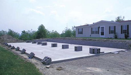
The pier and ground anchor foundation system has long been the common and accepted manufactured home support and anchorage system. It adapts easily to local site conditions, does not require a great deal of dimensional precision, and goes into place quickly. In the most frequently used configuration, piers are designed by our engineers to be installed under the main beams of the home sections, under the mating line of multi-section homes and at other points designated by the home manufacturer. Perimeter piers or blocks may also be a part of the home’s support system.
The most common pier types are steel jack stands or hollow core concrete masonry blocks with open cells placed vertically and stacked one on top of the other to the required height. These can be single stacks of blocks or double stacks, laid up in an interlocking configuration. Concrete block piers over 36 in. high should be configured as double block piers. Piers over 80 in. high take special considerations by the engineer.
Another pier type is the pyramid-shaped open frame, steel type with a support plate on top of an adjustable rod at the apex. The steel pyramids come in several heights and support prescribed/rated load capacities based on manufacturer’s testing. The pier height and building weight dictate the allowable spacing between the piers.
Ready to Order? If you are ready to order foundation plans, you may place your order by clicking here.
Piers set on square footers or pads on the ground spread the load from a pier over a larger area, making a more stable base. The square pad footers may be concrete, either poured in place or precast, preservative-treated wood, acrylonitrile butadiene styrene (ABS), or other materials approved by the local building authority and designed by our engineers. The spacing of the piers and the allowable bearing capacity of the soil determine the size of the footer or pad. The piers are typically vary depending on home design, local soil characteristics, and roof snow load.
The spacing of the anchors and the strap is specified by our engineers based on the size of the home and the wind zone. In HUD wind zones II and III, vertical straps from the sidewall of the home to ground anchors may be required in conjunction with the straps from the I-beam to the ground anchor. Our engineering analysis will show the tie-down sizes, capacities, and spacings on the plans we create for you.
COST OF CONSTRUCTION
The pier and anchor support system is the least initial cost for providing a support system for manufactured homes.
REAL PROPERTY CLASSIFICATION
In some instances, lenders and state and federal agencies do not consider pier and ground anchor support systems a real property foundation. Some exceptions are acceptable like cases where the anchors are held in place by means other than the soil alone, such as encasing the anchors in a concrete slab. These types of approaches are explored by our engineers when we design your plans.
INSTALLATION
The installation of a pier and ground anchor foundation system is frequently accomplished in one working day.
WIND LOAD RESISTANCE
On non-proprietary systems, the pier and anchor system is the one most often specified by our engineers as an effective means to resist wind forces.
GRAVITY LOAD RESISTANCE
A pier and anchor foundation supports gravity loads (live and dead) adequately. Our engineers take into account the bearing strength of the soil, and that the piers are properly spaced, and there are appropriate perimeter piers installed as required by the home manufacturer and the authority having jurisdiction.
SEISMIC LOAD RESISTANCE
Since the HUD standards have no provisions for seismic resistance design, almost all manufactured housing, (and, therefore, most pier and anchor installations) is not designed specifically to withstand seismic loads. Our engineers, however, analyze that a manufactured home is capable of resisting the highest seismic forces in the model building codes for your specific geographic region.
FLOOD RESISTANCE
The foundation type is suitable for use in flood plain areas when FEMA-recommended designs or designs meeting FEMA’s performance criteria are used. FEMA suggests taking the following precautions when a home is located in a flood plain: the anchor system should be designed to resist uplift floatation, collapse, and lateral movement under saturated soil conditions; and the floor level should be set above the 100-year base flood elevation. Under no circumstances should the home be located in a floodway.
FROST PROTECTION
In areas where frost is a design issue, individual anchors and footers under the piers are designed to below the frost line and bear on earth below that depth. As an alternative to running the footers below the frost line, holes for the footers may be dug to the frost depth and then back filled to the surface with gravel or other material that will not retain moisture. Another option is to insulate the area around the crawl space. This would eliminate the need to run the anchors and footings below the frost depth.
PIT-SET CRAWLSPACES
DESCRIPTION
The crawl space foundation system described here has two main distinguishing characteristics: it incorporates full perimeter wall support together with internal, independent support points; and the space itself is not habitable. Within that very broad definition, there are many styles, designs, and ways to build pit-set crawl space foundation systems. This section describes one design that has worked effectively with manufactured homes that we design for. Crawl space foundation systems are intended for use where a traditional site-built foundation look and feel is preferred. This foundation is less well suited for instances where economy, speed, or installation flexibility is paramount.
In some of our designs, the perimeter foundation wall rests on an excavated footer. The wall itself may be constructed of one or more conventional building materials (such as poured concrete, concrete block, or treated wood). The entire perimeter of the manufactured home floor bears directly upon this wall. The chassis is also fully supported, but with relatively economical piers. The manufacturer-designated ridge beam support points are carried by economical piers or posts. The home’s resistance to horizontal or uplift forces is achieved through attachment of the floor joists to the exterior foundation wall. No additional anchoring devices may be necessary – our engineers will determine this.
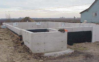
This foundation can be used on sloping lots and for recessed “low profile” installations. In the latter case, the structural walls form a barrier to the entry of water underneath the home and act as a short retaining wall. The low profile design, providing a site built “look,” is much more difficult to achieve with a traditional anchor set or slab foundation.
Ready to Order? If you are ready to order foundation plans, you may place your order by clicking here.
Access to the crawl space for utility hookups and repairs must be considered by our engineers. This is potentially problematic in a low-profile installation. One solution is for the contractor to install an access panel in an appropriate location, such as a closet floor.
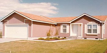
The low profile crawl space foundation system provides more of a site built appearance as shown below.
CONSTRUCTION
Crawl space foundation systems require more care and precision than conventional anchor systems. The exterior wall of the foundation should not exceed the dimensions of the manufactured home’s perimeter floor joists (not including the thickness of any exterior siding or sheathing). After staking the site, excavation to the depth of the footing is done with a backhoe. Interior footings may be individually dug with a power soil auger or poured as a grade beam. Some variations of this system allow placing interior piers on crushed rock.
As forms are constructed, they are double checked to make sure they are level, dimensionally accurate, and square. Reinforcing steel specified by our engineers is set as required. Concrete is poured, tamped, and dressed (e.g., anchor bolts are carefully placed for the sill).
Forms are stripped and the structure is again measured. The walls may also be constructed of mortared and grouted hollow core blocks, again with bolted sills. A third option is a concrete or block stemwall in combination with a wood-framed ponywall.
Pony walls are useful when a low-profile installation is either not possible or not desirable. They also afford the installer with a bit more dimensional tolerance when placing the home directly on the stem wall.
A well thought out plan for setting anchor bolts will prevent trouble later when installing the home. Bolts should be carefully placed so that they will not coincide with the floor joists. This is a matter of good planning and careful workmanship. Cutting off bolts or coring out the sill to allow for the bolt’s washer and hex nut is not recommended. Interior support footers, both along the chassis and at the ridge beam columns, may be poured concrete or crushed rock (if locally approved).
VENTILATION
Crawl space ventilation is provided through perimeter wall vent openings. Planning for vents varies, depending primarily on whether or not the home is being installed in a low-profile configuration.
INSTALLATION
Normally, the foundation, especially the low-profile version, is completed before the home arrives. The axles, tires, and hitches are removed, and the home is installed on the foundation by craning or rolling. Once placed on the foundation sill or pony wall, the floor is brought to a level position. Interior piers are placed along the chassis beams and positioned at the designated ridge beam columns.
Where an open endwall permits the truck to back the home inside the foundation, a home can be moved into position by the toter. Building the missing endwall then finishes the foundation.
There are a number of options for constructing the interior piers that carry the chassis and ridge beam loads to the ground. The most economical is approved dimensional lumber, such as redwood or treated fir. Also popular are non-grouted hollow core concrete blocks and manufactured steel piers. Since these structural components only provide vertical support, they may be selected for economy and ease of installation.
METHODS OF ATTACHMENT
The crawl space design allows attachment of the entire perimeter of the floor joist system to the foundation sill, the preferred and most economical approach. The connection is secured with engineer-approved nailing strips (or approved steel nailing plates), fastened according to our engineer’s nailing schedule. The strips may then be painted and left as a finished surface. If vinyl siding is to be applied over the sheathing, it is installed last.
Chassis piers may be placed and tightened to the chassis beam through compression, wedges nailed in place, spot welds, or a number of proprietary attachment devices.
CONSTRUCTION CHALLENGES
Typically, a crawl space foundation is fully constructed before a home is installed. This presents a few challenges to the foundation contractor and home installer:
- The foundation must be precisely measured and constructed. Installers/builders are advised to consult with the home manufacturer to obtain the exact floor dimensions. There is less tolerance for error than if the foundation were intended for a site-built home.
- The manufacturer must provide a “foundation ready” floor-chassis system. This involves recessing all steel chassis components 8�10 in. from the edge of the floor joists.
- The home is normally moved onto the foundation with rollers. If the site is not accessible from the street, a crane is used. The use of a crane is often the method of choice for multiple installations.
- Often, the working conditions under the home are cramped and dark, due to the enclosed perimeter.
- When placing a home in a “low-profile” installation, planning for adequate slope in the home’s drain line is important. If the home site and proximity is high enough above the street sewer, the drain line can be routed under the perimeter foundation footer; otherwise, a sleeve must be placed in the foundation wall to allow the drain to exit. Depending on the floor plan, the drain may need to be routed a substantial distance before it exits the foundation, creating potential problems with inadequate slope. Some manufacturers can supply “drops” through the floor and ship sufficient loose material to hang the drain line with proper slope.
Ready to Order? If you are ready to order foundation plans, you may place your order by clicking here.
COST
Crawl space foundation systems generally are more expensive than slabs and anchors but less than basement foundation systems. If carefully planned, savings gained in some parts of the system will pay for costs generated in other areas. For example, many times the cost of tie-downs (ground anchors) is eliminated in crawl space foundations and piers used for the support of the chassis may be scaled back significantly. These savings partly offset the additional costs associated with building a perimeter wall that both supports and finishes the home.
REAL PROPERTY CLASSIFICATION
A crawl space foundation system utilizing the perimeter load-bearing enclosure walls could be expected to meet the conditions for real property financing. With the structural perimeter wall, the home can be securely attached to the foundation to resist wind, gravity, and seismic forces.
INSTALLATION TIME
Installing a manufactured home on a perimeter wall crawl space foundation system is typically a two-step process, similar to an installation over a basement. First, the home is delivered alongside or near the foundation and uncoupled from the transporting truck. Next, the house is raised, the axles, wheels, and hitches are removed, and then it is rolled or craned onto the foundation. This is inherently slower than driving the home into its final setup position, as would be the case with an anchor and pier or slab system. A crew of three typically can construct the crawl space foundation system in three days before delivery and install and finish the home in five days after delivery (not including a garage or other ancillary structures).
WIND LOAD RESISTANCE
Although the areas where this system has been popular are not prone to hurricanes, pit-set crawl space systems offer effective resistance to the buffeting forces of high winds. The continuous fastening of the home’s floor joists to a sill ( i.e., anchored to a structural concrete wall and footing) provides good resistance to horizontal forces. Further, homes set in “low profile” offer less wall exposure to high winds thus reducing the loads required to be resisted by the connections.
GRAVITY LOAD RESISTANCE
The perimeter load-bearing enclosure wall support system provides excellent gravity load resistance. The perimeter wall carries much of the roof load directly to the earth. The chassis main beams and piers carry only the interior floor loads. The perimeter enclosure wall supports the full perimeter of the home.
SEISMIC LOAD RESISTANCE
The perimeter load-bearing enclosure wall support system combined with a deep stemwall provides adequate seismic load resistance. The structural connection of the home to the perimeter foundation wall can be designed by our engineers to effectively transfer the forces to the earth around the foundation. This system has been used effectively in the San Francisco Bay Area, one of the highest seismic risk zones in the nation.
FLOOD RESISTANCE
The low-profile version of the crawl space foundation system described here is not intended for use in floodplain areas. However, when FEMA-recommended designs are specified, crawl space system foundation systems are suitable for use in floodplains. Among the FEMA requirements are the following: the foundation system resists flotation, the floor level is set above the base flood elevation, and the home site is not in the floodway.
FROST HEAVE
As long as the footers reach to below the maximum frost depth, crawl space foundation systems can be and have been used in any climate.
CONCRETE SLABS ON-GRADE
DESCRIPTION
A slab system designed by our engineers is a foundation that is considered to provide all necessary structural support to a manufactured home in an economical manner. The home is typically elevated above the slab, creating what appears to be a conventional crawl space under the home. However, to distinguish this group of foundations that, even in the coldest climates, sit above the frost line and are monolithic (i.e., the home sits on a single, integrated structural element), they are separately classified.
A slab is designed by our engineers that supports the home on top of the earth. The slab is uninsulated or insulated (same as a frost protected shallow foundation), depending on the local conditions and judgment of our engineers.
In this regard, the term “slab,” when applied to manufactured housing has a slightly different meaning than it does when used with stick-built homes. A slab used for a stick-built home is considered to be at once a structural support for the rest of the building (as it is for a manufactured home), and a semi-finished floor, over which linoleum, tile, wood, or carpeting is installed as the finished surface. All manufactured homes are delivered with full raised floors that include insulation and finished surfaces as well as electrical and plumbing systems and, in most areas, heating/cooling ducts. The slab under a manufactured home, therefore, does not act as the home’s floor, but rather as a platform for the home.
Slabs are not unique to manufactured homes. They are recognized and accepted for many other types of buildings, including site-built single-family homes and commercial structures. They are commonly found in areas with freezing and expansive soils.
Ready to Order? If you are ready to order foundation plans, you may place your order by clicking here.
Part of the reason slabs are economical is that they are relatively thin, extending only as deep as required to carry the structural loads. In northern climates with deep frost depths, the slab generally does not run to below the frost line. In such cases, the slab (often referred to as a “floating” slab) can shift as the soil underneath expands and contracts due to forces such as frost heave. This movement can be minimized or eliminated if the ground under the home is kept dry through the use of effective drainage techniques, such as drain tile and sump pumps. In contrast, properly designed crawl space and basement foundations remain fixed, even if the adjacent soil moves. The propensity of uninsulated slabs to shift with soil movement may keep them from meeting state or local requirements for a real property foundation and therefore from qualifying for real property financing.
An insulated slab (frost protected shallow foundation) is insulated around its perimeter, which keeps the ground under the slab warmer than the surrounding soil. For this design (commonly referred to as a shallow frost-protected foundation) to work during the coldest months, the crawl area ventilation must be closed to prevent cold outside air from cooling the space under the home and freezing the soil beneath the slab. The modest heat loss through the floor of the home keeps the crawl area warm and the insulation traps the heat in the soil, thus providing a heat sink that minimizes the chance of the ground freezing under the home. Although subject to review by the local authority, this design variation may qualify as a real property foundation.
The simple design of slabs minimizes the time required for fork work and
provides a level base for the home.
ADVANTAGES
The primary attraction of a slab is its relatively low cost. Due to the normal rectangular shape of the slab, the time and materials required for forming are minimal, compared to other concrete designs. Because there are no footings or piers extending down into the earth below the slab itself, in areas that have deep frost lines or expansive soils, the savings can be significant when compared to deep piers.
DISADVANTAGES
As noted earlier, uninsulated slabs are not typically used for homes intended to meet real property requirements. However, in areas where there is no frost or a relatively shallow frost line, the cost to qualify the foundation may be modest.
If the manufactured home will have an attached garage (which we can also engineer and create plans for), it may not be possible to economically pour a single slab for both structures, due to the vertical height difference between the garage slab and the floor of the house. The two foundations can be separated by an expansion joint, as any variation in movement between the home and the garage could be structurally damaging to either or both. Possible differential movement between adjacent slabs should be considered. A slab is less suitable than other designs for sloping lots. In most such instances, it is necessary to excavate to a level site (“cutting a level pad”).
CONSTRUCTION
A slab must be designed by our engineers to handle points of concentrated loads, such as centerline (ridge beam) piers, or distributed loads, such as along exterior walls. The slab must be able to resist upheaval pressure from the ground below and not fail to act as a structural unit or monolith.
A number of techniques and materials are used by our engineers to reinforce a slab. The variables that impact rigidity and durability include the overall thickness of the concrete and the incorporation of various types of reinforcing that are encased in concrete.
The use of post-tensioning, while not common for relatively lightweight construction applications like manufactured homes, is nevertheless a way to dramatically increase the strength and load-carrying capacity of concrete slabs.
SLAB VENTILATION
With rare exceptions, there is no difference between slab, anchor and pier, and crawl space foundations with respect to ventilation requirements. Adequate ventilation is needed to dissipate moisture migrating into the area under the home from other sources. Vents are normally provided in the exterior wall or the skirting surrounding the home. As with other foundations, provision for cross ventilation is essential. The area beneath a manufactured home installed on a slab is accessed through an opening in the exterior containment wall or skirting.
INSTALLATION
Generally, slabs offer a ready subsurface for the installation of a manufactured home. The home is merely driven over the slab for assembly. The hard and level slab provides an ideal working surface for the installers to complete the connection between foundation and home. Once rough-spotted, the close-off plastic can be stripped and the two (or more) sections leveled and mated together. The materials used for crawl space foundations can also be used for a slab. The most popular piering material is the hollow core concrete block. These blocks can be used at our engineered-specified points along the chassis I-beams and the mating wall, the latter for support of the ridge beam. Alternatively, a fabricated steel stanchion with screw thread cap can be used.
METHODS OF ATTACHMENT
To act in unison with its slab foundation, a home must be permanently anchored to the foundation. This is commonly accomplished through the use of anchors embedded in the concrete that our engineers analyze and design. Homes can also be permanently affixed through welded or bolted connections between the chassis and the piers, if the piers are themselves permanent. Examples of permanent piers are mortared and grouted concrete blocks, and steel stanchions bolted to the slab. The permanent attachment may also be through a structural, load-bearing exterior wall.
CONSTRUCTION CHALLENGES
Relative to basements and crawl space foundations, the slab offers fewer construction and installation challenges. Slabs are commonly poured somewhat wider and longer than the homes for which they are intended. Thus, less precision is required in their layout and preparation.
The uppermost challenge is the need to pour a high quality, well-reinforced singular mass of concrete, as it will literally become the ship upon which the house will sail in heaving soil conditions. There cannot be any chance of failure or breaking into disconnected sections, the consequences of which could be severe for the home.
A garage with a slab floor adjacent to the home’s floor need to be carefully designed by our engineers to offset pour and expansion joints between home and garage. Otherwise, any weak points in the concrete between the house and garage could grow to a large structural problem if the monolith separates under pressure and were to move independently of each other. This could create structural damage at the point where the house and garage connect.
COST
The overall cost of a typical slab, and the attendant material and labor to install a manufactured home upon it, falls in the low to mid-range of all foundations covered by this guide. More concrete is consumed than in simpler ribbon footing crawl space foundations. However, less form construction and less restrictive dimensional tolerances create savings. But the dramatic savings results from not having to excavate or pour concrete to any significant depth in the ground. Consequently, the relative cost savings increases in areas with deep frost lines.
REAL PROPERTY CLASSIFICATION
Except in the case of uninsulated slabs in areas with deep frost penetration, slab designs may be made to meet requirements for real property financing. In particular, insulated slabs and slabs used in areas with no frost penetration may meet the FHA real property criteria.
INSTALLATION TIME
A slab creates an ideal environment for the house installation process: The home’s footprint is over a firm, clean, and often dry platform. Level concrete is perfect for the safe and rapid lifting of a home with manual jacks to remove the wheels, axles, and hitches, and to rest the home upon its supports. These advantages usually speed up the installation process.
Ready to Order? If you are ready to order foundation plans, you may place your order by clicking here.
WIND LOAD RESISTANCE
A slab is an excellent base to which a house can be permanently secured with ground anchors embedded in concrete. After we engineer the anchorage and it is properly installed, these anchors can give a home the horizontal resistance necessary for wind load resistance. Because of varying wind load potential and standards across the country, our engineers design the anchorage device that is site specific for your exact home dimensions and geographic conditions.
GRAVITY LOAD RESISTANCE
Weight loads from the manufactured home and its future contents are designed by our engineers to be transferred to the ground and spread over a considerable area by the slab. This assures that the foundation can support the home even in the lower ranges of soil-bearing capacity.
SEISMIC LOAD RESISTANCE
In higher seismic zones, slabs are required to meet more stringent design and engineering requirements. A foundation system that is designed to move under pressure from the earth below is less suitable for use in the higher seismic risk zones. Seismic loads may be engineered by our staff that involve detailing connections for large withdrawal loads and the possibly designing the slab as a reinforced “structural mat” foundation.
FLOOD RESISTANCE
Although no home should ever be installed in a floodway, slabs can be used successfully to support homes located in the flood plain provided the floor of the home is above the 100-year base flood elevation. Knowledge of the soil upon which the slab is to be poured, with respect to its behavior when saturated, will help decide whether a slab is the best foundation selection in a flood plain. Standing water may act to scour the area under a shallow foundation, impairing its performance once floodwaters recede.
FROST HEAVE
After being designed by our engineers and correctly installed, slabs can resist the forces of frost heave. The two major strategies by our engineers: insulating the slab and taking steps to keep the ground under the slab dry (e.g., use of drain tiles) are proven and successful measures. Uninsulated slabs in frost-prone areas may be subject to shifting when exposed to frost conditions.
BASEMENTS
DESCRIPTION
A basement is both an engineered structural support system for a manufactured home and a substantial addition to the livable space of the home. This makes the basement unique among the classes of foundations described in this guide.
After our engineers are finished, the basement becomes an integral part of the mobile home design (including site-built homes), particularly in the northern half of the country, from the Intermountain West to the Northeast. Their popularity in this region stems from the basement’s ability to give a home excellent support, even in deep frost locations, and to generate relatively inexpensive living space. This living area is particularly important to families whose outdoor activities are curtailed in the winter.
The popularity of basements in colder climates is readily apparent from the census data. Basements account for upward of 4 out of every 5 site-built home foundations in the 33 states that comprise Zone 3 of the HUD thermal standards . In the Northeast and north central states, the preference for basements climbs to 9 of every 10 homes.
Basements are well suited for sloping lots, especially lots that slope down to the back of the home. This allows our engineers to design a “walk-out” basement, featuring doors to a rear yard. Indeed, many developers create special grades to accommodate a walkout basement. If the development site is relatively level, the grading plan will call for substantially elevated pads upon which to perch the homes.
Basements are natural for “low profile” installations. Basements are typically designed by our engineers to support the full perimeter wall of the home. Typically, supports for the interior of the home are provided at the marriage line. Posts are designed by our engineers to carry the loads transferred by the floor joists and cross beams that support the chassis. Basements can be built partially or entirely above ground, creating in essence a two-story, or a split- level manufactured home. This application suggests even more varieties for home placements. Upslope lots can be developed with basements that incorporate a garage that is directly accessible from the street.
| Ready to Order?If you are ready to order foundation plans, you may place your order by clicking here. |
CONSTRUCTION
Basements demand extreme care in their construction. The outside wall cannot be longer or wider than the floor of the manufactured home. If such a construction error is made, the remedy can be very expensive, or can result in a very awkward correction. The basement walls should never protrude horizontally beyond the edge of the perimeter floor joists.
Obviously, the excavation of a large quantity of soil presents a disposal problem. A certain amount of earth can be used to backfill against the basement wall to create drainage slope away from the house. But the exporting of soil becomes a budget item not usually encountered when using slabs or crawl space foundations.
Balancing the soil helps to minimize this by excavating less of the basement than would normally be anticipated. With this plan, the basement walls extend 3 or 4 ft above the natural site grade. Earth removed from the excavation is used as backfill to create a substantial grade away from the house and bring the grade to within 8-10 in. from the bottom of the floor.
Because of the size of the structure, basements require far more material (typically concrete and/or concrete blocks, if specified) than other foundations. Up to 90 cu yds or more can be for a basement for a larger two-section mobile home.
Depending on the type of basement and the method used to install home sections, the basement may or may not be fully completed before the home arrives. Homes that are to be rolled onto cross-beam girders need to have the top 6-8 in. of wall (or the top course of concrete blocks) left out, to permit the home to be rolled across the basement walls and into final position.
A well thought-out plan for securing the home to the foundation by our engineers prevents trouble later when installing the home. Since bolts can interfere with the floor joists, foundation straps may be preferable. Cutting off bolts or coring out the sill to allow for the bolt’s washer and hex nut is not recommended.
Most basements incorporate usable space and are accessed through stairwells from the upper (main) level. Walk-out basements have standard exit doors to the outside yard. In any case, a code-complying access must be incorporated into the structure’s design.
VENTILATION
A basement is usually intended to become part of the habitable space of a home and direct ventilation to the outside is not recommended. Therefore, only ventilation that can be controlled by the homeowner is used. Doors, if it is a walkout basement, and operable windows, if they are part of the design, allow natural ventilation.
Basements are often conditioned (heated and cooled), with ducted supply and return assuring adequate air changes. When the basement is part of the conditioned space, the equipment size will need to be adjusted accordingly. In such cases, the home manufacturer must be consulted for requirements covering adequate air flow, ducting, protection against heat loss, etc. A basement that will be heated by the manufactured home’s system adds greatly to the burden of the mechanical plant, and must be accounted for by the manufacturer when sizing the heating system, ducts system, and electrical system.
INSTALLATION
It is more challenging to install a manufactured home on a basement than on slab or crawl space foundations. Inevitably, the home’s sections will be maneuvered over substantial vertical heights. Many contractors who set up homes on slabs or crawl spaces are not well equipped to handle a basement. The two primary methods of installing homes on basements are the crane and the roller systems, as described below:
Crane set: Perhaps the more common of the two processes, a crane picks up and places each home section directly on the basement walls (and cross girders, if used). This permits the basement to be more fully complete before the home arrives. Provisions must be made, however, to withdraw the crane’s straps before they are trapped between the basement and the home.
A basement may also pose structural issues for the manufacturer. For example, manufactured homes in most cases are required to have a number of shearwalls that carry the loads from the wall and roof diaphragms to the foundation. These shearwalls are supported by multiple joists under each wall. Since this is a unique feature of these homes, special provisions must be made for connecting/anchoring of the multiple shearwall joists and shearwall end columns to the foundation system to ensure adequate transfer of the loads.
For a crane installation to go quickly, the setup crew and the crane operator must be experienced with this process, an appropriate strap spreader device must be used, the homes must be at the site and in position for pickup, and the crane must be able to set up fairly near the basement.
Strap (or cable) withdrawal can be accomplished by measuring and cutting portions of the sill (make sure that the foundation approvals permit this), then replacing them after the straps are pulled out. A good way to avoid trapping the straps between the sections of the home is to set the second module onto jack posts at the center line that are set at a slightly high position. The home will come down and rest in a canted posture that allows removal of the straps. The jacks can then lower the home into a level position.
The cost of using a crane varies by location. Rates are highly variable; some crane operators charge high minimums, others charge steep rates for travel time, so it is wise to shop around. In normal conditions, a two-section home can be set and made weather-tight in 4 hours.
Roller system: Popular for all types of manufactured home installations, the use of rollers is an effective way of moving homes forward, sideways, and up or down mild slopes. Rollers are best suited to place a home over an enclosed foundation system, especially a basement.
Ready to Order? If you are ready to order foundation plans, you may place your order by clicking here.
Contractors can set up the temporary columns, rails, channels, and roller devices rapidly. Special column supports are used for basement sets. Typically 2 or 3 such rails are used. The home is simply pushed sideways over the basement walls and rolled into final position. Using hydraulic jacks, the home is then lowered onto the sills and cross beams, if used. In either case, the axles, tires, and hitches are removed before the home is lifted onto or rolled over the basement.
Basement showing backfill to create drainage slope.
INTERIOR SUPPORTS
The supporting structure of a basement depends on whether the home has a standard or integrated floor system.
Standard floor system: The majority of manufactured homes are built with floor joists running either parallel or perpendicular to the length of the home and framed by perimeter joists. The floor assembly of each section of the home rests on the steel chassis, consisting of two steel I-beams. The design of most manufactured homes requires support for the chassis I-beams at several points, as well as at designated points along the marriage wall. Under HUD regulations, the chassis may not be removed from the manufactured home.
Foundations, including basements, must accommodate a home’s support requirements. Thus, basements for manufactured homes commonly feature heavy steel cross beams, for transferring the load to the basement walls, and columns in the center of the basement for marriage line support. Our engineers design these structural support elements.
Integrated floor system: An alternative design to the conventional chassis system is the integrated floor system. An integrated floor consolidates the floor joists and the chassis into a single structure. The home then has lower transportation and installation profiles, and is supported at the perimeter and centerline wall. This has obvious advantages for basement applications, as it typically eliminates the need for steel crossbeams and provides more flexibility in locating a stairwell to the basement.
METHODS OF ATTACHMENT
The basement design allows the entire perimeter length of the floor joist system to be attached to the top of the sill, the preferred and most economical approach – our engineers may suggest another method depending on your situation. The connection is secured with engineer-approved nailing strips (or approved steel nailing plates), fastened according to our engineer’s nailing schedule. The strips may then be painted and left as a finished surface.
Some states, such as Minnesota, have specific requirements for connections between the basement sill and a home’s floor to allow the soil pressures applied against the basement wall to be resisted by the floor diaphragm. If vinyl siding is to be applied over the sheathing, it is installed last.
CONSTRUCTION CHALLENGES
The basement is fully constructed before the home is installed. This presents a few challenges to the foundation contractor and home installer:
- The basement must be precisely measured and constructed. Installers/builders are advised to consult with the home manufacturer to obtain the exact floor dimensions and coordinate these dimensions with the engineered plans. There is less tolerance for error than if the foundation were intended for a site-built home, because such errors cannot be corrected by the floor framing carpenters, as they can when site building a home.
- The location and design of all under-floor utilities and structures (for example, drain lines, heat duct crossovers, steel chassis components, and axle hangers) must be considered in advance.
- The manufacturer must provide a “foundation ready” floor/chassis system, with steel chassis components sufficiently recessed to allow an 8-10 in. clearance from the edge of the floor joists. Alternatively, the manufacturer must construct the home on a floor/chassis system designed to allow a clear span between the basement wall and the marriage wall.
- Unless special precautions are taken, including coating the exterior of the walls with a water- tight sealant, basements are particularly susceptible to water penetration. We try design a water-tight sealant into all of our basement foundation plans.
- The home manufacturer must provide a stairwell design that permits entry to the basement.
COST
Basements are expensive compared to other types of foundation systems. However, basements can add significant amounts of usable space to a home.
REAL PROPERTY CLASSIFICATION
Properly designed basements would be expected to meet the conditions set for real property financing. Because the walls and connections are properly engineered by our team, basements effectively resist wind, gravity, and seismic forces.
INSTALLATION TIME
Constructing a basement requires more time than other foundation systems and, as indicated, is more complicated and requires a greater degree of precision. However, most of the site work is completed prior to the arrival of the home. Once the transporter delivers the home, the installation contractor positions the home over the basement either using the crane or roll-on methods described earlier. In either case, basement installations require more time than other systems
WIND LOAD RESISTANCE
With proper fastening of home to foundation, basements effectively resist wind loads. Due to the firm attachment techniques designed by our engineers and into every basement, the homes are well protected and secured to the ground.
GRAVITY LOAD RESISTANCE
In general, our basement designs offer good gravity load resistance. The weight of the home is transferred through the load-bearing walls or columns to the footers. In most cases, connections, even at the perimeter wall, are economically made.
SEISMIC LOAD RESISTANCE
Although earthquake risks are relatively low in most areas where basements are popular, the mass and depth of a basement, coupled with the attachment methods, offers good resistance against the effects of shaking from ground motion.
Ready to Order? If you are ready to order foundation plans, you may place your order by clicking here.
FLOOD RESISTANCE
Due to the fact that a basement can easily fill with water during a flood, this system is not recommended when building in a flood plain. In fact, the basement floor is considered the first floor of a residence under the FEMA National Flood Insurance Program. As such, it would fall below the base flood elevation level for such a home, and the home would not qualify for flood insurance.
FROST HEAVE
Full basements will have footings and concrete floors below any known frost line in the United States. Walkout basements, on the other hand, may need extra deep footings because the exit door threshold will be at grade level. Overall, basements are relatively impervious to frost-induced movement.